Air-Fuse™ Balance Check™ Grip-Clamps® Roller-Cam Clamps™ Shim Block Assemblies™
Aladco® manufactures grippers, clamps, and shim block assemblies on a per-order basis. If you are interested in purchasing any of these products, please contact Aladco® 262-544-5994
Air-Fuse™
Product Overview
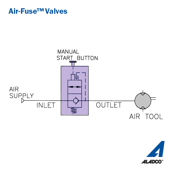
The Air-Fuse™ valve, designed specifically for pneumatic applications, is a patented Aladco® product. The Air-Fuse™ valve monitors air circuits. In the event of broken air lines, the valve stops all air flow, preventing whipping hoses.
Air-Fuse™ Valve Resources:
Disclaimer:
- Technical details subject to change without notice
Features:
- Superior, self-cleaning ball seal provides long product life
- Exceeds ANSI Class VI Leak Standard (bubble tight)
- Body is made of high strength, lightweight, anodized 6061 aluminum alloy
- Designed for use with lubricated or non-lubricated air systems
- Tamper resistant with no required maintenance
- Operating pressure 30 to 120 psi; Operating temperature 30° to 150° F
- Activates when air pressure drops to 20 psi
- Airflow is stopped 100% to allow for repair
- Manual start button will not reset until airline repair is made
- Patented and Made in Waukesha, Wisconsin USA
- Standard 3-year warranty
Balance-Check™
Product Overview
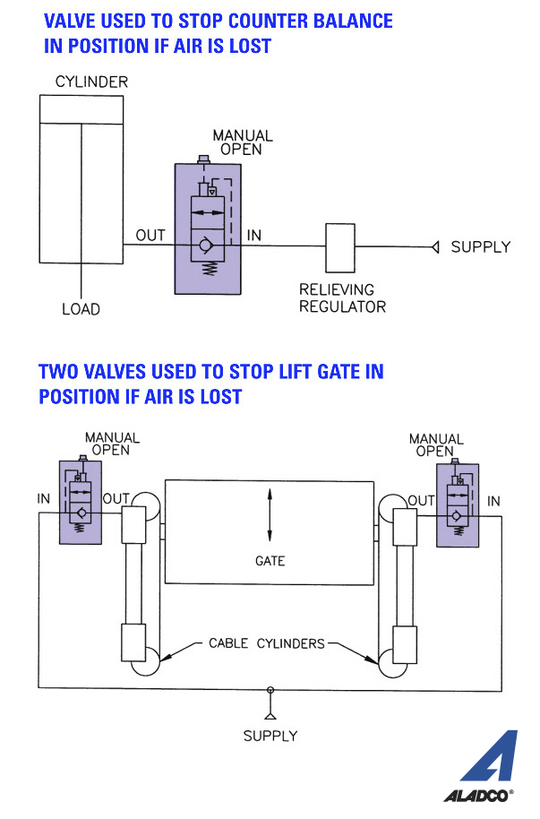
The Balance-Check™ valve, designed specifically for pneumatic applications, is a patented Aladco® product. The unique bubble-tight seal keeps 20 psi of air in the cylinder to form an air cushion. This valve is commonly used on air balancers.
Balance-Check™ Valve Resources:
Features:
- Superior, self-cleaning ball seal provides long product life
- Exceeds ANSI Class VI Leak Standard (bubble tight)
- Body is made of high strength, lightweight, anodized 6061 aluminum alloy
- Designed for use with lubricated or non-lubricated air systems
- Tamper resistant with no required maintenance
- Prevents load drift
- Operating pressure 15 to 150 psi; Operating temperature 30° to 150°F
- Patented and Made in Waukesha, Wisconsin USA
- Standard 3-year warranty
Disclaimer:
- Technical details subject to change without notice
Grip-Clamps®
Product Overview
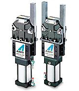
Aladco® offers a line of pneumatic Grip-Clamps® ideal for automotive, food and other industrial manufacturing requirements. Special heat-treated, alloy steel components offer superior wear and strength. Adjustable cushions provide smooth, long operation. Standard arms allow for a wide range of tooling clearances. We offer toggle lock and power lock clamps allowing greater flexibility to fit all your manufacturing needs.
Toggle vs Power
The toggle clamp is used for added safety and is designed so that the linkage goes over-center and remains in a positive locked position even in the absence of air pressure. The toggle clamp is unlocked only by the cylinder powering the linkage back through the over-center locked position.
The power lock is designed so that the linkage does not go over-center providing for variable clamping thicknesses.
We recommend the use of Aladco® check valves for toggle and power applications to maintain air pressure and clamping force.
Grip-Clamp® Resources:
Grip-Clamp® 2501 – One Arm Toggle Lock Information
Grip-Clamp® 2502 – Two Arm Toggle Lock Information
Grip-Clamp® 2506 – 90° Toggle Lock Information
Grip-Clamp® 2511 – One Arm Power Lock Information
Grip-Clamp® 2512 – Two Arm Power Lock Information
Grip-Clamp® 2516 – 90° Power Lock Information
Features:
- 2500 Grip-Clamp® Family:
- The largest gripper available – 10,900 inch-lbs. clamping force
- Arm torque load capacity of 56,000 in-lbs
- Powered by a 4.0″ bore cylinder
- Grip-Clamp® mechanically toggle locks in the over-center clamped position
- Standard 90-degree arm openings
- Custom arms and special openings available
- Enclosed 1.0″ cylinder rod prevents rod failure
- All heat treated precision ground alloy steel components for reliability
- Grease fittings for re-lubrication
- NFPA mounting to fit a quality cylinder
- Hydraulic cylinder option available
- Patented and Made in Waukesha, Wisconsin USA
Please Note: The 2600 Grip-Clamp® Family is no longer in production. Contact Aladco® for information about a rebuild or repairs.
Roller-Cam Clamps™
Product Overview
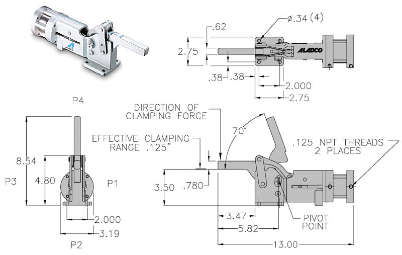
The Roller-Cam Clamp™ has specialized applications and is a patented Aladco® product. The lightweight, compact clamp is ideal for fragile material handling such as glass and plastics. The clamping force is controllable and does not apply a crushing pressure. It has a unique variable clamping range of 0” to 0.12” to accommodate material variations and stacking tolerances.
The clamp’s engineering design and material strength provide a dependable, durable product to fit your clamping needs.
Roller-Cam Clamp™ Resources:
Features:
- Controllable clamping force
- Eliminates crushing pressures
- Accommodates material variations and stacking tolerances
- Variable clamping range is 0 to 0.12″
- Eliminates frequent tooling adjustments
- Standard 70 degree arm opening
- Superior size-to-holding force ratio
- Lightweight and compact in size
- Enclosed 0.75″ cylinder rod prevents rod failure
- Powered by a 2.0″ bore cylinder
- All heat treated, precision ground alloy steel components for reliability
- Patented and Made in Waukesha, Wisconsin USA
Please Note:
- Aladco® Roller-Cam Clamps™ are legacy products. Supplies of new units are limited.
- Repair of Roller-Cam Clamps™ by Aladco® is also available.
Shim Block Assemblies
Product Overview
Shim block assemblies are used anywhere a locating position must be held accurately, but also needs to be adjustable. Typically, they are used in sets of two or three for the X & Y/Z locations of a tooling or fixture plate.

Features:
- Quick and inexpensive way to locate and mount tooling plates and components
- Available in 2 standard sizes
- Simple to adjust location by grinding shim to size or adding an additional shim
- All needed hardware included
- Made from low carbon steel with black oxide finish
- Made in Waukesha, Wisconsin USA
Shim Block Assembly Resources:
Application Example
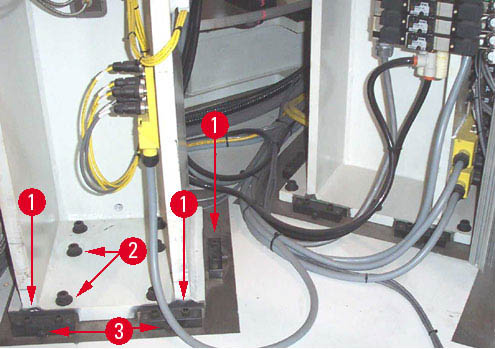
The shim block assemblies are mounted against the surface and against the tooling and then tightened down securely with all screws at item #1 & #2. Measurement would then be made to find where tooling is in reference to where it should be. Screws at item #2 & #3 would be loosened so that grinding shim can be removed. Shim will then be ground to size from the initial location measurement. When grinding to the desired size is completed, the shim is put back in, screws at item #3 are tightened which will move the tooling as they are being tightened. Finally, screws at item #2 are tightened and tooling is now located at the new dimension.
